 DE
DE  BG
BG  IT
IT  GR
GR 

User's manual for LED clock timer display of Rousis Systems LTD.
The functions of the infrared remote control for the LED timer clock are described below. The remote control working with a maximum range of 20 meters, with visual contact and focus on the panel.
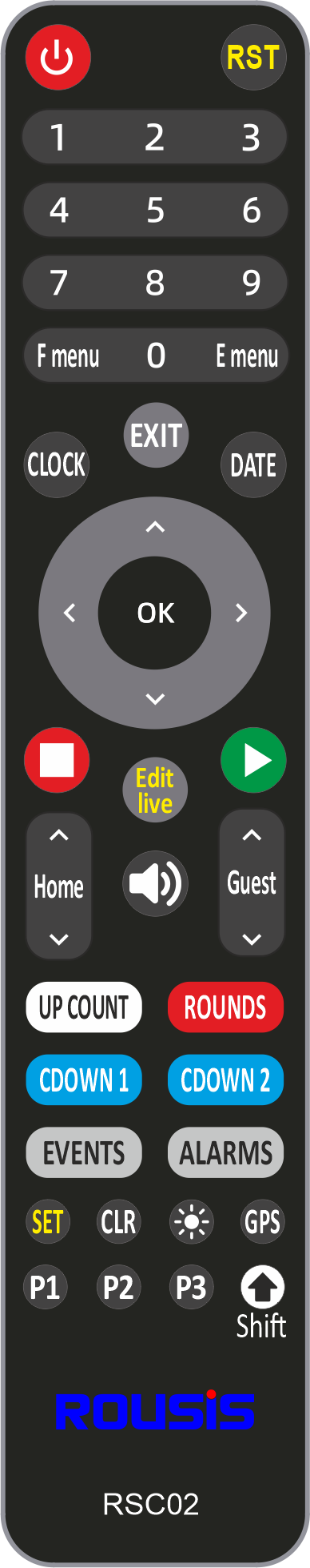 Remote Control Button functions
![]() Display ON/OFF
Display ON/OFF
![]() Reset the program
Reset the program
F menu Opens the F' menu of options (table of this bellow)
E menu Opens the E' menu of options (table of this bellow)
EXIT Escape from menu, set or timing.
CLOCK Sets the clock
DATE Sets the date
![]() Stop the timer
Stop the timer
![]() Start the timer
Start the timer
Edit live Change the timer interbal while is running
![]() Sounds the horn
Sounds the horn
Home Changes the core of the home player or team with up and down arrows
Guest Changes the core of the guert player or team with up and down arrows
UP COUNT It starts counting up
ROUNDS It starts the rounds program game
CDOWN 1 It starts the countdown timing 1
CDOWN 2 It starts the countdown timing 2
![]() + ROUNDS Sets the rounds program
+ ROUNDS Sets the rounds program
![]() + CDOWN 1 Sets the countdown time 1 (HH:MM:SS).
+ CDOWN 1 Sets the countdown time 1 (HH:MM:SS).
![]() + CDOWN 2 Sets the countdown time 2 (HH:MM:SS).
+ CDOWN 2 Sets the countdown time 2 (HH:MM:SS).
![]() Shows on rhw display the level of the brightness
Shows on rhw display the level of the brightness
Description of menu F options
| F1 | Select info to display (time-date-temp). * | Default: 1 |
| F2 | Select display tempo for time, date and temp. | Default: 9 |
| b | Set LED Brightness 0-16 (0 = use onboard sensor for auto adjust) | Default:16 |
| L | Sets the brightness level for open-close the out relay (with 2units hysterisys) | Default: 16 |
| F5 | High resolution temperature with decimal digit | Default: 0 |
| F6 | Countdown alarms number (how many) | Default: 0 |
| F7 | Alarm Lenght (in seconds) | Default: 0 |
| F8 | Clock dots blinking enable | Default: 1 |
| F9 | Clock Alarms Enable |
*Select info to display
|
Code
|
Clock
|
Date | Temperature |
|
1
|
ON
|
OFF
|
OFF
|
|
2
|
OFF
|
ON
|
OFF
|
|
3
|
ON
|
ON
|
OFF
|
|
4
|
OFF
|
OFF
|
ON
|
|
5
|
ON
|
OFF
|
ON
|
|
6
|
OFF
|
ON
|
ON
|
|
7
|
ON
|
ON
|
ON
|
Description of menu E options
| E0 | Display digits (please don't chage) | Default: 4 |
| E1 | Invert display (for some models fo inverted diplay ) | Default: 0 |
| E2 | TLC LED drivers | Default: 0 |
| E3 | Separate temperature (for special displays) | Default: 0 |
| E4 | Centimeter of a second (timekeeping in hundredths of a second) | Default: 0 |
| E5 | External control inputs (for buttons or relays etc)* | Default: 0 |
| E6 | GPS Synchronize Enable | Default: 0 |
| E7 | Buzzer On | Default: 1 |
| E8 | 2 Digits timer modes* | Default: 0 |
| E9 | Time zone set (for GPS synchronization) | Default: 0 |
*External control code:
- Keypad Control Off = 0
- Buttons input (Start,Stop, Reset) Up Counter = 1
- Buttons input (Start,Stop, Reset) Counter Down 1 = 2
- Buttons input (Start,Stop, Reset) Counter Down 2 = 3
- Monitor mode (displays only serial data from Pro Timing software)
* 2 Digits timer modes
- Normal 2 digits timer with hours-minutes-seconds = 0
- 0-59 timer = 1
- 0-99 timer = 2
- 59-0 timer (Counter down non finish) = 3
- 99-0 timer (Counter down non finish) = 4
Input instructions cable connection
(For models with input cable for external control of the timer.)
| white | Reset |
| Yewllow | Stop |
| Green | Start |
| Brown | GND (-) |